
Home
>
Products > Industrial Components
> Motor Cores
>
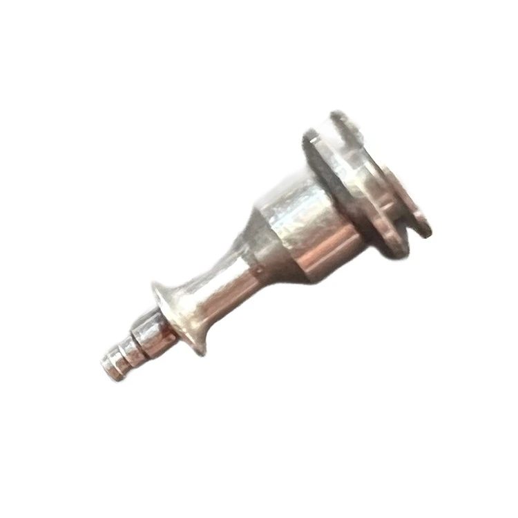
Solenoid Plunger Replacement Armature Core for Hydraulic And Pneumatic Valves


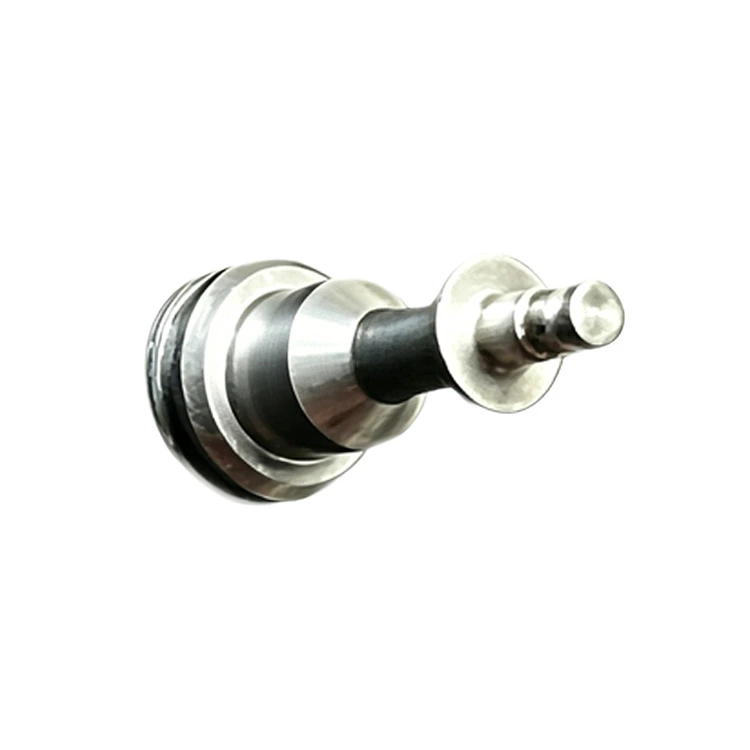
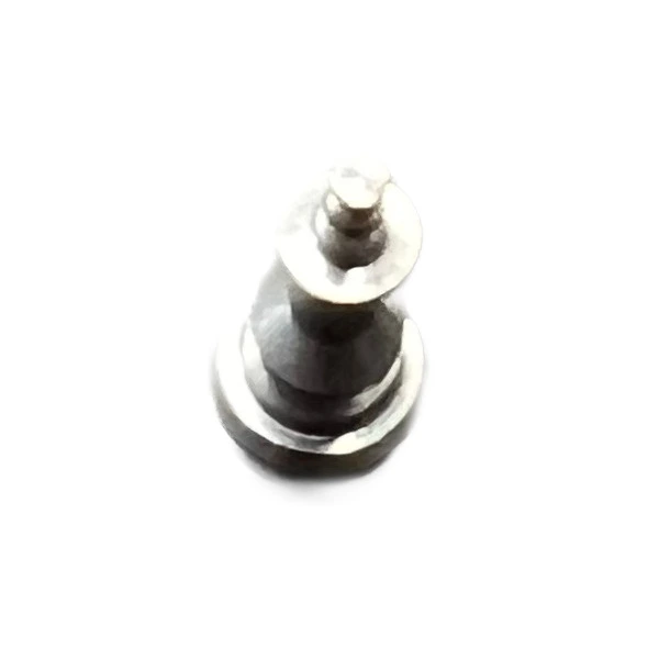
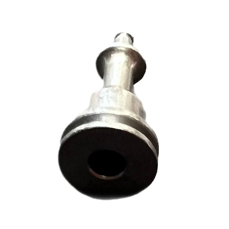

Solenoid Plunger Replacement Armature Core for Hydraulic And Pneumatic Valves
This is a replacement Solenoid Plunger Replacement Armature Core for Hydraulic And Pneumatic Valves from Qimao Metal Manufacturer. The kind you find in hydraulic systems and air lines. The old one stops moving or gets stuck. You pull it out and need a new one that fits exactly. That is what we make. We turn these from stainless steel bar on CNC lathes. The material is usually 430F or 430FR because it responds to magnetic fields. No coating required. The outer diameter gets ground to a smooth finish so it slides inside the valve body without binding. Some have grooves. Some have a stepped nose. We cut whatever your old part looks like. Send us a sample or a drawing.
Send Inquiry
Product Description
Qimao Metal Manufacturer’s quality Solenoid Plunger Replacement Armature Core for Hydraulic And Pneumatic Valves from Qimao Metal Manufacturer product material options: 430FR stainless steel (standard) or 430F for better machinability. Stroke range: 0.5mm to 5mm depending on valve series. Thread size: M3 to M6 on the pushrod end, or plain type for sliding armatures. Operating temperature: -20°C to +120°C (-4°F to 248°F). Sealing style: soft O-ring captured type or metal-to-metal lapped seat. Each core is centerless ground to a smooth finish of Ra0.4μm or better. We also supply the return spring, guide bushings, and sealing washers if needed. Every batch is tested for pull-in force and release timing on a real solenoid test rig, not just a visual check.


Product Parameter (Specification)
|
Material |
Length (mm) |
Width (mm) |
Weight (g) |
|
Steel
|
22.4 |
12.6 |
2.06
|
Product Feature
1. Made from magnetic stainless steel We make this Solenoid Plunger Replacement Armature Core for Hydraulic And Pneumatic Valves use 430F or 430FR grade. These alloys respond to the solenoid coil. When the coil energizes, the plunger moves. Cheap plungers use non magnetic steel and barely shift. Ours pull clean every time.
2. Precision ground outer diameter The outside surface gets ground after turning. This removes any taper or waviness. The finished plunger slides inside the valve bore with a few tenths of clearance. Not too tight. Not too loose.
3. Cut to your exact length We do not stock random sizes. You give us the length from your old plunger. We cut within plus or minus one thousandth of an inch. No trimming needed on your end.
4. Grooves machined where specified Some valves have grooves for lubrication or pressure balancing. We can add these. Straight grooves. Spiral grooves. Stepped grooves. Just show us the pattern on your old part.
5. Chamfered ends for smooth entry Both ends get a small angle cut. This helps when you push the plunger back into the valve body. No sharp edges to scrape the inside bore or damage the seal.
6. Flat or radiused nose available Some plungers have a flat end that hits a stop. Others have a rounded nose that seats against a rubber pad. We can do either. Tell us what your valve uses.
7. No burrs left behind Every plunger gets hand inspected under a magnifier. If we feel a burr with a fingernail, it goes back to the bench. You should never cut a seal on installation.
Application
1. Factory automation lines – When pneumatic cylinders start hesitating or staying open too long, the old plunger core is often the real culprit. Swap this Solenoid Plunger Replacement Armature Core for Hydraulic And Pneumatic Valves in during a planned downtime to restore cycle consistency without replacing the whole valve bank.
2. Hydraulic power units – For clamping, lifting, or mold injection systems, a worn armature core causes pressure drop at the moment of shifting. This replacement keeps your proportional or on/off hydraulic valves responding cleanly, especially at low voltages.
3. Truck and heavy equipment air systems – Pneumatic suspension, brake release, or transmission shift valves use small solenoid plungers that rust from condensation. Our 430FR core resists moisture corrosion better than plain steel, and the geometry matches common commercial vehicle valve bodies.
4. Water treatment plants – Diaphragm valves controlled by solenoids often cycle 24/7. When the original plunger loses its sealing edge, the valve starts chattering. A fresh armature core restores tight shutoff without the cost of a new pilot valve assembly.
5. Oil and gas pilot valves – Remote wellhead or pipeline venting valves need armatures that don’t stick after months of no movement. The low residual magnetism design of this core breaks away cleanly, so the valve won’t fail-to-close when you need it most.
Product Installation & Usage Tutorial
Step 1 – Depower the valve and release all pressure from the system. Remove the coil nut and slide the coil off the tube.
Step 2 – Unscrew the Solenoid Plunger Replacement Armature Core for Hydraulic And Pneumatic Valve’s manual override or the end cap. Pull the old armature core and spring out using non-magnetic tweezers (don’t scratch the tube bore).
Step 3 – Check the inside of the guide tube for burrs or rust. Wipe it clean with a lint-free cloth and a little clean hydraulic oil.
Step 4 – Place the new spring onto the new core, then insert both into the tube. Make sure the rubber seat or metal tip faces the valve body.
Step 5 – Reinstall the end cap or stop nut. Torque it to finger tight plus a quarter turn – over-tightening can bind the plunger.
Step 6 – Slide the coil back on, tighten the nut, and cycle the valve manually (if possible) before applying full pressure. Done.

Hot Tags: Solenoid Plunger Replacement Armature Core for Hydraulic And Pneumatic Valves, China, Manufacturer, Supplier, Factory, Customized, Quality, Cheap, Made in China
Related Categories
Send Inquiry
Please feel free to fill your inquiry in the form below. We will reply you in 24 hours.
Related Products


X
We use cookies to offer you a better browsing experience, analyze site traffic and personalize content. By using this site, you agree to our use of cookies.
Privacy Policy